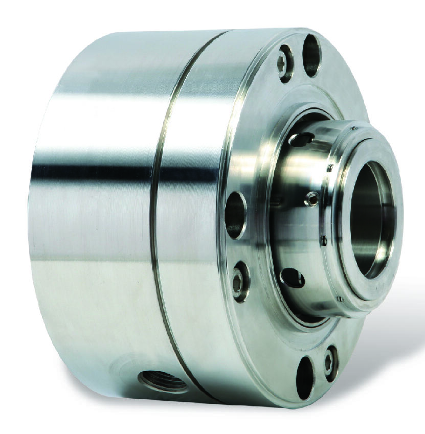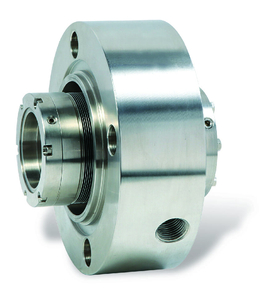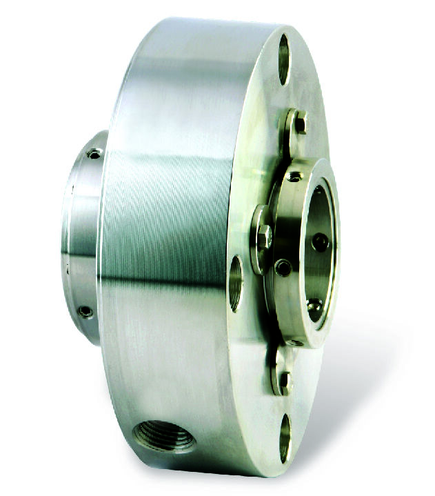
GEV53A is used in situations where the leakage of the transported medium to the atmospheric side is not allowed. It consists of a double-end face seal and the sealing fluid between the faces. The sealing fluid is contained in a seal tank, and the pressure in the tank is higher than the pressure of the sealed medium. If the internal seal leaks, the sealing fluid leaks into the transported medium, causing the liquid level and pressure in the seal tank to drop.
I. Scope of Application
PLAN 21 System
Primarily used in applications requiring reduced seal chamber temperatures, such as pumps handling high-temperature hot water or centrifugal pumps in chemical processes with elevated medium temperatures. This system diverts medium from the pump discharge through an orifice, cools it via a heat exchanger, and injects it into the seal chamber. It is suitable for clean liquids with temperatures not exceeding 120°C.
PLAN 52 System
A non-pressurized system providing buffer fluid for tandem mechanical seals, mainly used in applications where minor leakage could cause contamination, such as centrifuges in the pharmaceutical industry or mixing equipment in the food industry. This system supplies buffer fluid from an atmospheric-pressure tank, typically at ambient pressure.
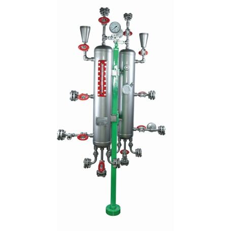
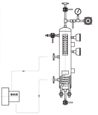
PLAN 53A System
A pressurized dual-seal containment system designed for hazardous, toxic, or crystallization-prone media, commonly used in petrochemical hydrogenation units and pharmaceutical reactors. This system utilizes a nitrogen-pressurized accumulator to maintain stable isolation fluid pressure, typically 0.15–0.2 MPa higher than the process medium pressure.
PLAN 53B System
An externally pressurized isolation system using a hydraulic source, suitable for applications lacking nitrogen supply or requiring higher pressures, such as offshore platforms or remote oil transfer pumps. This system employs an external hydraulic pump to generate pressure, with a maximum working pressure of 10 MPa.
II. Usage Methods
Pre-Startup Preparation
- Inspect all piping connections for tightness and ensure instruments such as pressure gauges and level indicators are functional.
- For PLAN 52, fill the buffer tank to 80% capacity via the vent valve.
- For PLAN 53A/B, use a dedicated oil filling pump to circulate and vent until pressure stabilizes.
Pressure Setting and Adjustment
- For PLAN 53A, adjust the nitrogen pressure reducing valve to the target pressure.
- For PLAN 53B, activate the hydraulic pump and gradually increase pressure to the set value.
- After setting pressures for all systems, observe for 30 minutes to ensure stability.
Operational Monitoring
- PLAN 21: Monitor heat exchanger differential pressure, with normal fluctuations not exceeding 0.15 MPa.
- PLAN 52: Monitor buffer fluid pressure, with normal fluctuations within ±5% of the set value.
- PLAN 53A: Monitor nitrogen pressure, with normal fluctuations within ±0.05 MPa of the set value.
- PLAN 53B: Monitor hydraulic pressure, with normal fluctuations within ±2% of the set value.
Routine Maintenance
- Weekly: Check isolation fluid color and clarity; replace immediately if cloudy. Inspect all pipe connections for leaks using soap solution.
- Monthly: Calibrate pressure gauges. For PLAN 52, clean the vent valve.
III. Common Issue Handling
PLAN 21 Reduced Cooling Efficiency
- Verify cooling water flow meets or exceeds 80% of the design value.
- Check plate heat exchanger differential pressure; clean if it exceeds 0.1 MPa.
- Validate temperature sensor accuracy.
PLAN 52 Excessive Buffer Fluid Consumption
- May indicate minor primary seal leakage or clogged tank vent valve.
- Add dye to locate leakage points.
- Inspect and replace 0.5 μm filter cartridges.
PLAN 53A/B Pressure Abnormalities
- If pressure drops continuously, first check nitrogen pressure.
- If nitrogen pressure is normal, inspect for isolation fluid leakage, focusing on heat exchangers.
- If nitrogen pressure is abnormal, replace the bladder in the accumulator.
IV. Precautions
Safety Requirements
- PLAN 53A systems must not use oxygen as the gas source.
- For hydrogen sulfide service, use specialized isolation fluids.
- Regularly inspect safety valves during operation.
Environmental Adaptability
- In Arctic regions, equip PLAN 53B systems with electric tracing.
- In tropical regions, increase PLAN 21 cooling capacity by 30%.
Emergency Response
- Immediately shut down the system if pressure drops to zero abruptly.
- Activate emergency cooling if isolation fluid temperature exceeds 90°C.
V. Technical Support Services
The company has established a customer after-sales emergency response mechanism. Always refer to the installation and maintenance manual for the specific model during operation. Contact our engineering team promptly for technical support in special working conditions.
Copyright © Jiangsu GOLDEN EAGLE Fluid Machinery Co., Ltd. - Privacy Policy