Reactors are critical equipment in the petrochemical and related industries, serving as one of the primary production units in the overall chemical process. The shaft seal assembly is one of the most frequently failing components in the reactor—and even the entire process system. Typically, components such as bearings, gearboxes, and motors are installed above the shaft seal. Whenever the shaft seal requires maintenance or repair, these upper shaft-end components must first be removed, resulting in cumbersome disassembly, prolonged downtime, and high costs.
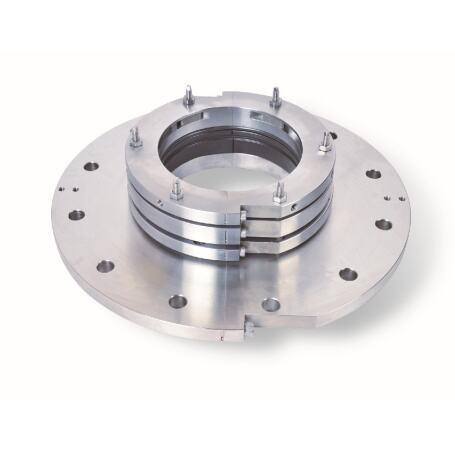
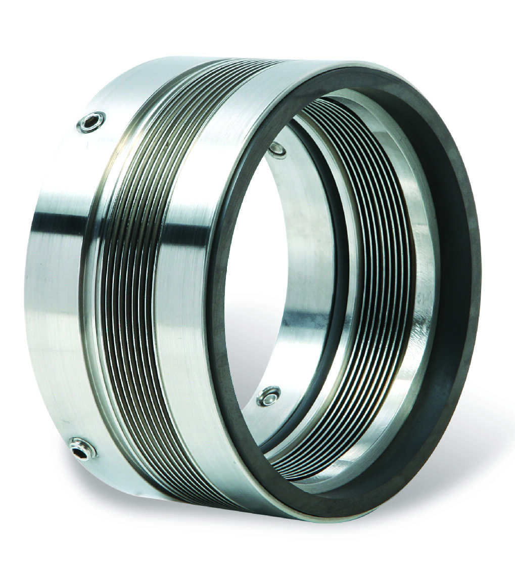
To address this challenge, we have dedicated efforts to the research and development of split mechanical seals, enabling the replacement of mechanical seals without disassembling any shaft-mounted components.
Common Material Combinations
Sealing Faces: Graphite, Silicon Carbide, Aluminum Oxide
Secondary Seals: NBR, FKM, EPDM
Metal Components: 304, 316L, 2Cr13, Duplex Steel
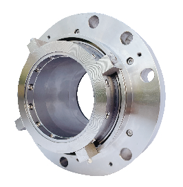
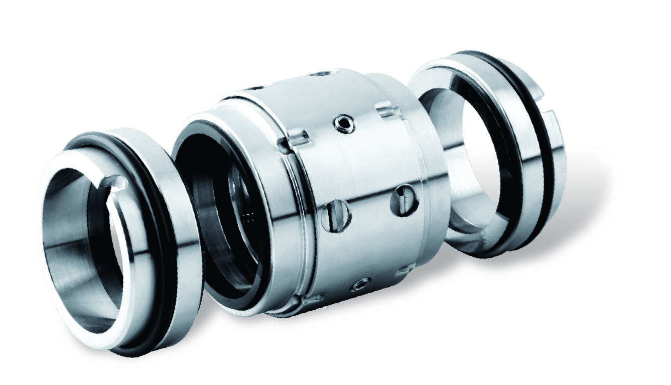
Structural Description
Single mechanical seal, unbalanced type, dry-running design
Operating Parameters
Temperature: -10°C to 150°C
Surface Speed: 2 m/s
Pressure: 6 bar (0.6MPa)
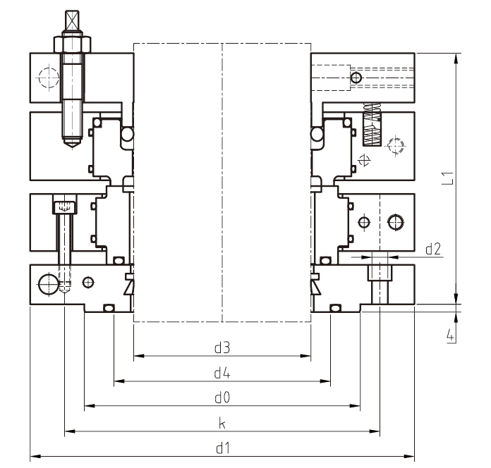
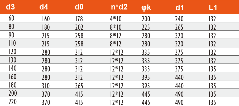
Metric dimensions (mm), with sizes above 220mm available for customization.
I. Scope of Application
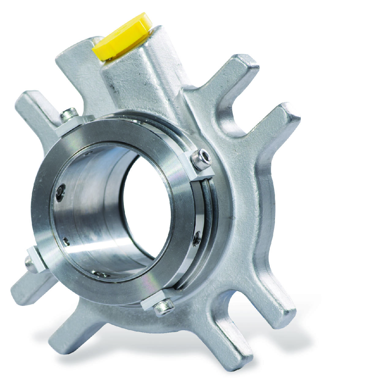
Fully Split Seals for Pumps
Mainly used for shaft seal maintenance in various centrifugal pumps and mixed-flow pumps, particularly suitable for critical process flows where prolonged shutdowns are not permitted. Typical applications include circulation pumps in water supply systems, cooling water pumps in power plants, and process pumps in the petrochemical industry. This type of seal can be replaced without disassembling the pump body or motor.
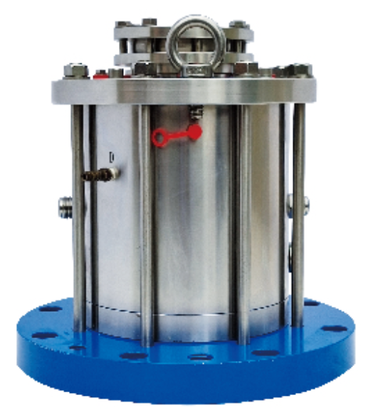
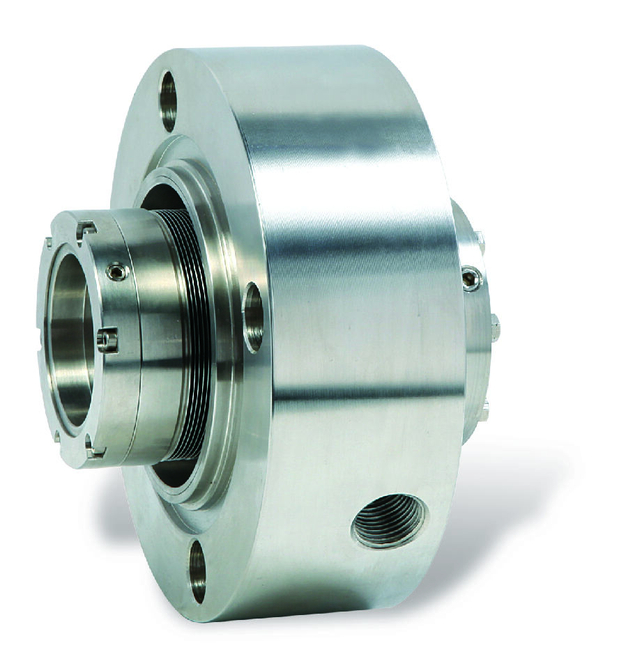
Fully Split Seals for Agitators
Designed specifically for large reaction kettles and mixing tanks, suitable for agitation equipment in the chemical, pharmaceutical, and food industries.
II. Usage Methods
Pre-Installation Preparation
- Clean the shaft surface to ensure it is free of burrs and corrosion.
- Check the equipment bearing clearance to confirm it is within the allowable range.
- Prepare specialized installation tools, including split fixtures, guide sleeves, etc.
On-Site Installation Steps
- Slide the split components onto the shaft in the marked order, using specialized tools to ensure proper alignment of all components.
- Evenly tighten the connecting bolts to the torque values specified in the technical manual.
- After installation, manually rotate the shaft to confirm no sticking or obstruction.
Operation and Debugging
- Perform a static pressure test before the first startup to verify seal performance.
- Operate at low speed for 2 hours, checking leakage and temperature rise.
- Gradually increase to the working speed while monitoring vibration and temperature changes.
Maintenance
- Check seal leakage weekly and record data.
- Inspect fastener tightness monthly.
- Examine seal face wear quarterly.
- Conduct a systematic overhaul annually.
III. Common Issue Handling
Leakage After Installation
- First, check if all split surfaces are aligned and ensure positioning pins are properly installed.
- Next, verify that the tightening torque is evenly distributed.
- Finally, confirm that secondary seals are correctly installed and undamaged.
Abnormal Noise During Operation
- This may be due to excessive component clearance or dry friction in the friction pair.
- Immediately shut down the equipment to inspect seal face contact.
- Ensure the lubrication system is functioning properly.
- Check whether component clearances meet requirements.
Short Service Life
- Focus on checking whether the medium contains abrasive particles.
- Verify whether the seal selection is correct for the application.
- Inspect equipment for excessive vibration.
- Confirm the flushing system is operating normally.
IV. Precautions
Installation Environment Requirements
- The on-site ambient temperature should be between 5°C and 40°C, with relative humidity not exceeding 80%.
- Avoid installation work in dusty environments.
- Ensure adequate lighting in the work area before installation.
Tool Usage Specifications
- Use only specialized tools provided by the original manufacturer.
- Violent installation methods such as hammering are strictly prohibited.
- Regularly calibrate torque wrenches.
Safety Precautions
- Display safety warning signs at the installation site.
- Wear safety harnesses for elevated work.
- Avoid rotating parts during equipment debugging.
V. Technical Support Services
The company has established a customer after-sales emergency response mechanism. Always refer to the installation and maintenance manual of the corresponding model for specific operations. If technical support is required for special working conditions, please contact our engineering team promptly.
Copyright © Jiangsu GOLDEN EAGLE Fluid Machinery Co., Ltd. - Privacy Policy