Primary Applications:
Compressors, blowers, and related rotating equipment.
Common Material Combinations:
Sealing Faces: Graphite, Silicon Carbide, Tungsten Carbide
Secondary Seals: NBR, FKM, EPDM, FFKM
-Metal Components: 304, 316, Hast.C, Duplex Steel, Titanium
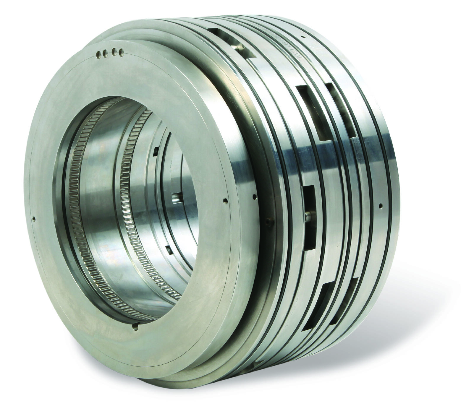
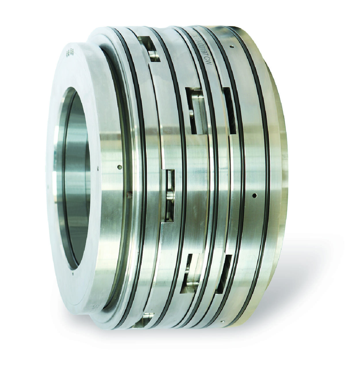
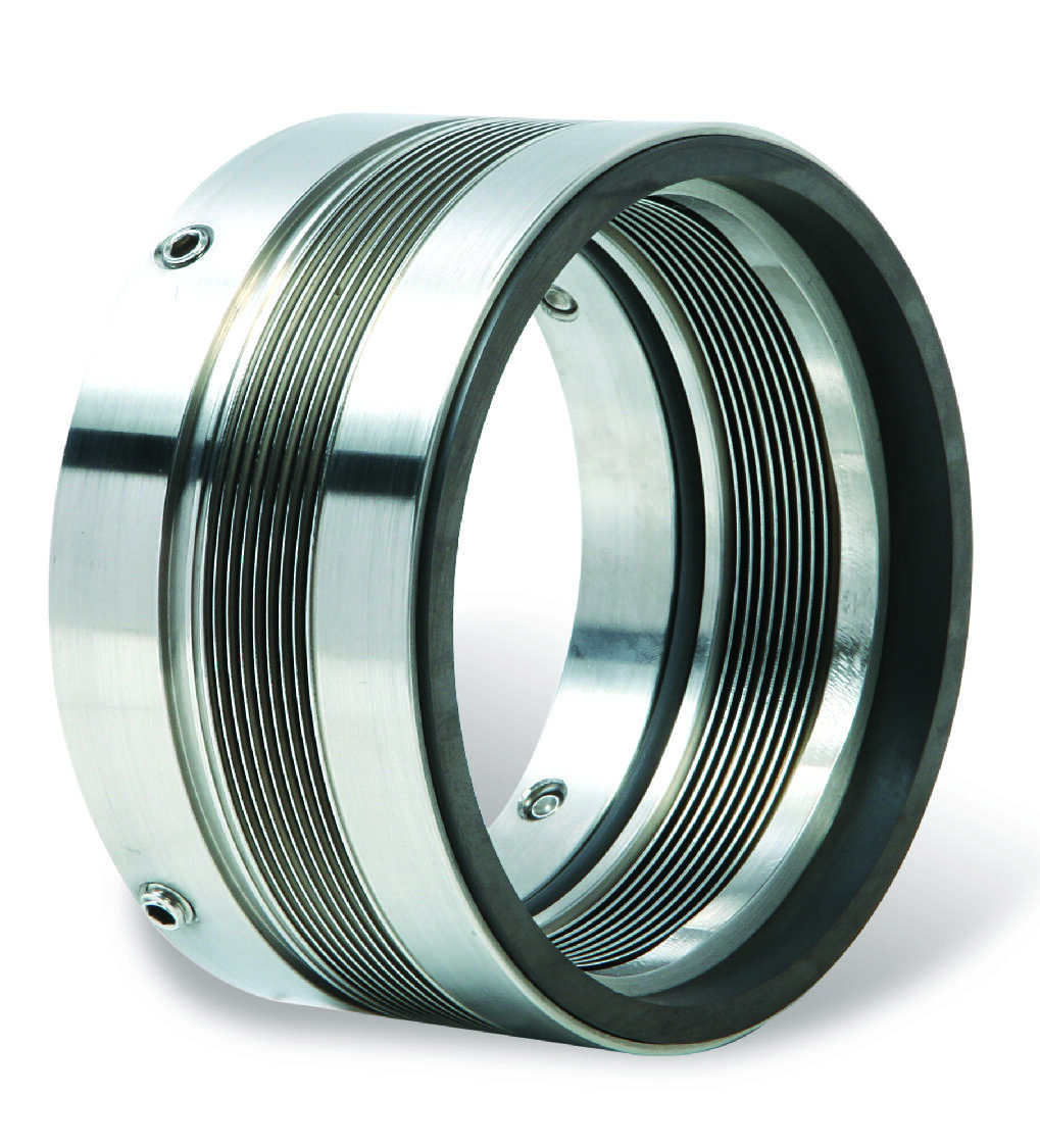
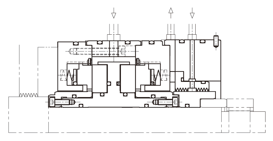
Structural Description:
Back-to-back double cartridge dry gas seal, balanced type, with trailing labyrinth seal.
Operating Parameters:
Temperature: -20°C to 230°C
Surface Speed: 150 m/s
Pressure: 120 bar (12MPa)
I. Scope of Application
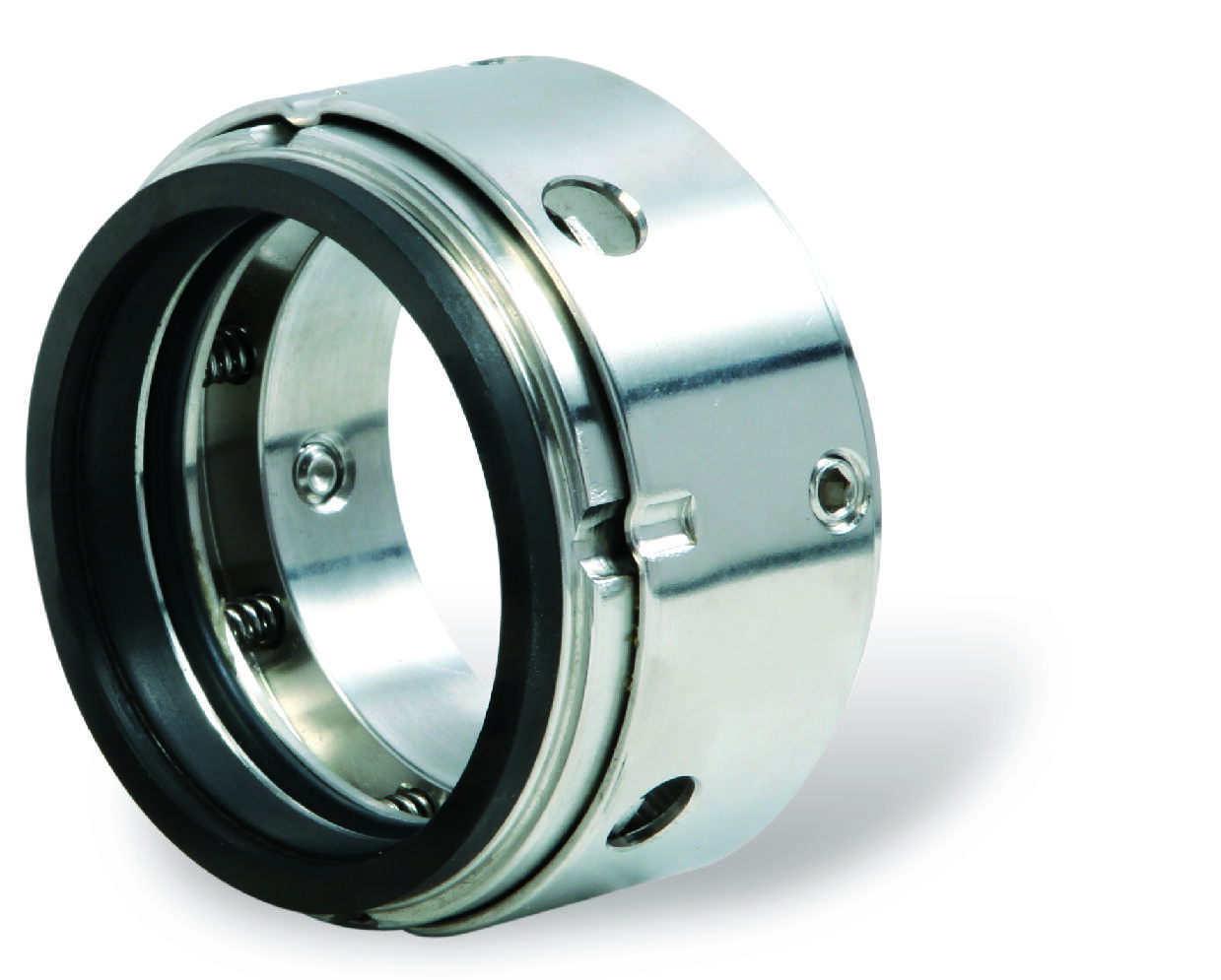
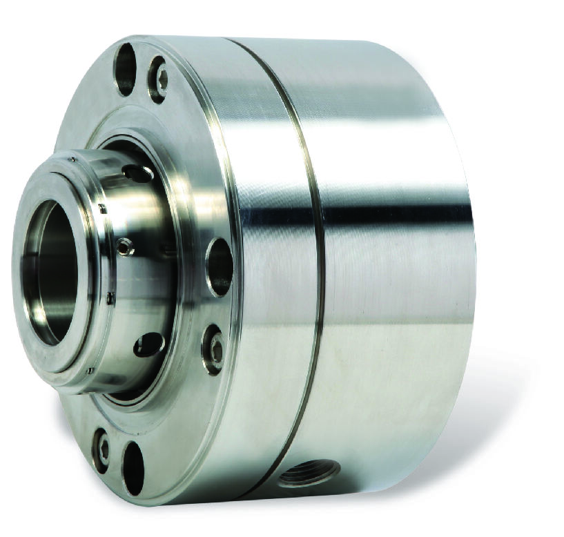
Single Dry Gas Seal
Mainly used for gas medium sealing in rotating equipment such as compressors and centrifugal pumps. Typical applications include natural gas transmission, syngas compression, and inert gas handling. This system utilizes aerodynamic grooves to generate hydrodynamic effects, enabling non-contact operation. It is suitable for clean gas conditions with working pressures up to 10 MPa.
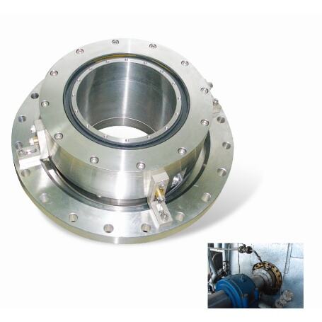
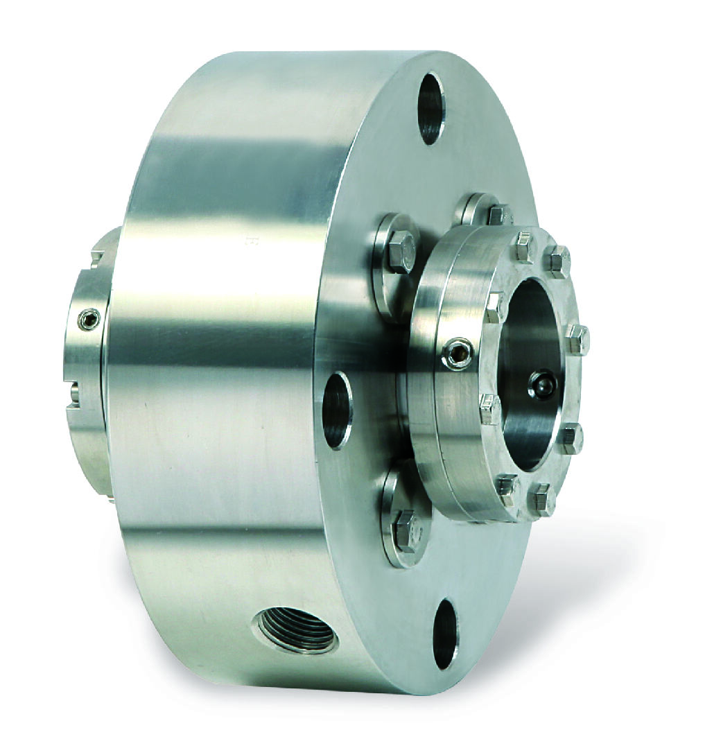
Double Dry Gas Seal
Designed for handling hazardous gas media, primarily used in hydrogenation units in petrochemical plants and syngas compressors in coal chemical processes. This system is configured with two dry gas seal faces to create an intermediate isolation chamber, making it suitable for sealing gas media with high hydrogen sulfide content or other toxic and hazardous gases.
Tandem Dry Gas Seal
Suitable for high-pressure conditions and applications requiring higher safety levels, commonly used in natural gas pipeline transmission and gas storage injection/production. This system features two stages of seal faces arranged in series, capable of withstanding working pressures up to 20 MPa, providing additional safety protection in case of primary seal failure.
II. Usage Methods
Pre-Startup Preparation
- Check the differential pressure indicator of the filter to ensure the filter element is intact.
- Inspect all instrument piping connections for tightness.
- Verify that the sealing gas source pressure and flow rate meet design requirements.
- For double seals, confirm the supply parameters of the isolation gas in advance.
Sealing Gas Pressure Setting
- Adjust the pressure reducing valve to maintain sealing gas pressure 0.2–0.5 MPa higher than the sealed medium pressure.
- For tandem seals, set the primary sealing gas pressure 0.3–0.6 MPa higher than the medium pressure, and the secondary sealing gas pressure at atmospheric or slightly positive pressure.
Operational Parameter Monitoring
- Closely monitor sealing gas consumption, which should remain stable under normal conditions.
- Monitor the temperature rise of the seal chamber, which should not exceed 40°C above ambient temperature during normal operation.
- Regularly check the gas composition at the vent port and investigate immediately if abnormalities are detected.
Routine Maintenance Requirements
- Record sealing gas pressure and flow data daily.
- Check filter differential pressure weekly; replace the filter element if it exceeds 0.05 MPa.
- Calibrate pressure sensor zero points monthly.
- Sample and analyze seal face wear quarterly.
III. Common Issue Handling
Abnormal Increase in Sealing Gas Consumption
- First, check if the sealing gas supply pressure is too high.
- Then, investigate whether the filter is clogged.
- Finally, use vibration analysis to determine if the seal faces are worn.
- If seal face damage is confirmed, schedule a shutdown for replacement.
Excessive Seal Chamber Temperature
- This may be due to liquid carryover in the process gas, friction between seal faces, or cooling system failure.
- Start by checking the quality of the process gas and ensuring the gas-liquid separator is functioning properly.
- Then, inspect the operating parameters of the seal cooling system.
- If necessary, shut down the equipment to examine the condition of the seal faces.
Monitoring System Alarms
- For low-pressure alarms, check the gas supply system and pressure reducing valve.
- For high-flow alarms, inspect the seal faces for wear.
- For high-temperature alarms, immediately check the cooling system and process gas condition.
IV. Precautions
Gas Source Quality Requirements
- The sealing gas must be clean and dry, with particulate matter no larger than 3 microns and oil content not exceeding 1 ppm.
- In cold regions, take special care to prevent liquid carryover in the sealing gas from freezing.
Special Condition Responses
- During plant startup and shutdown, ensure the sealing gas pressure always exceeds the process medium pressure.
- When handling media containing solid particles, add a high-efficiency filter before the sealing gas system.
Safety Protection Measures
- For hazardous media conditions, a leakage detection system must be installed, and vent ports must be directed to safe areas.
- Critical units should be equipped with a backup sealing gas source to ensure automatic switching in case of main gas source failure.
V. Technical Support Services
The company has established a customer after-sales emergency response mechanism. Always refer to the installation and maintenance manual of the corresponding model for specific operations. If technical support is required for special working conditions, please contact our engineering team promptly.
Copyright © Jiangsu GOLDEN EAGLE Fluid Machinery Co., Ltd. - Privacy Policy